|
1 Introduction 介绍
20MVA的变压器通常用于ITER交流电流测试平台到晶闸管的转换器提供实验功率。然而,由于ITER测试平台的大的系统阻抗,从而降低变压器阻抗的要求通常在实际变压器行业满足。本文将简要介绍如何变压器的阻抗降低至3%,以保证短路测试脉冲电流的要求。如何确保符合用户的测定值变压器阻抗要求,以确保基本平衡的关键是变压器设计的三相阻抗。The transformer of 20MVA is commonly used to ITER AC current testing platform to provide experimental power for thyristor converters. However, due to large system impedance of ITER testing platform, the requirement of reducing transformer impedance is commonly met in actual transformer industry. This paper will give a brief introduction of how to reduce transformer impedance to 3%, in order to ensure short-circuit test pulse current requirements. How to ensure compliance with the measured value transformer impedance requirements of users and to ensure basic balance is the key to the three-phase impedance of the transformer design.
2 The main technical parameters and load conditions of transformers变压器的主要技术参数和负载条件
2.1 The main technical parameters
与20MVA的额定容量,能够1000MVA下工作0.5秒,10kV的/0.4kV的额定电压,为50Hz,3%,与该三相阻抗不平衡率不超过10%的短路电阻的额定频率,加入群Yd11,并一一绝缘等级水平。
With rated capacity of 20MVA, able to work under 1000MVA for 0.5s, rated voltage of 10kV/0.4kV, rated frequency of 50Hz, short circuit resistance of 3 percent, with which the three-phase impedance unbalance rate does not exceed 10%, join group of Yd11, and insulation rating level of eleven.
2.2 Load conditions
提供交流电源至可控硅变换器,转换器的负载是感应性负载。验证短路故障条件下,直流侧的负载转换器的动态稳定的特点。变压器必须能够提供所需的短路电流,最大短路电流冲击,以350KA的冲击,短路试验时间为0.5s,不小于4h两个短电路测试时间间隔。Provide AC power to thyristor converters, converter load is an inductive load. Verify that the DC side load converter dynamic stability characteristics under short-circuit fault conditions. Transformer must be able to provide the required short-circuit the impact of current, the maximum short circuit current impact to 350kA, short circuit test time is 0.5s, two short circuit test intervals of not less than 4h.
3 Transformer impedance design calculations变压器阻抗设计计算
Due to the low short-circuit of the pulse transformer is with low voltage, and large electric current, so the key is of the transformer impedance design is to calculate transformer impedance and to estimate impedance of copper wire under low voltage.
3.1 Transformer impedance design calculations
Considering the cost of transformer is highly influenced by the level of transformers impedance, the key is to design reasonable structure of low impedance transformer. There are three majormethods to reduce the two-winding transformer impedance as following. The first is to increase the core diameter was reduced a small number of turns increases the potential of winding turns. The second is to increase the electrical winding resistance that increases the height of the core high window. The third is split high and low voltage windings of the transformer impedance requirements of this article is only 3%, well below the normal capacity is 20MVA transformer impedance, not less than 8%. After considering the above three methods adopted by the special electromagnetic design optimization software to calculate and determine the impedance transformer body is 1.9%.
3.2 Impedance transformer low estimate of copper wire
The low voltage transformer rated current up 28,867.5A, but this article requires closed delta connection. According to industry experience manufacturing low voltage high current transformer special "take the lead copper Low impedance transformer body impedance of 55%, that is 1.9 * 55% = 1.045%.
3.3 Calculation of the overall impedance transformer
Whole body impedance transformer impedance and low-impedance copper wire, namely 1.9% + 1.045% = 2.95%.
4 Structural design of the transformer winding and lead变压器绕组和引线的结构设计
To meet the convenience transformer wiring and ensure that the transformer has a high mechanical strength and good resistance to shock pulse short circuit capacity, low-voltage wire winding and structural design of the transformer to take appropriate measures, as follows.
4.1 Transformer high voltage winding of the structural design
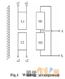
The transformer high and low voltage windings were split into equal volume of two windings disposed axially down, similar to the structure of the axial double split, and through external leads connected in parallel as figure 1. Segmented cylindrical of high voltage winding, two parts winding around the system as a whole, the whole cast. Low uses foil winding, winding two parts were cast; using a special technology of suit does not make the top and bottom halves displacement between the windings.
4.2 Structural design of low voltage copper wire
Structure and low voltage transformer connection copper wire using the up and down two sets of low voltage windings connected to each triangle separately, then the corresponding phase by vertical copper connected in parallel to achieve "in the middle row of vertical copper leads to a three-phase outlet. This makes it easy lead copper solid and reliable support and positioning. Copper wire structure and connections, see figure 2.
5 Transformer impedance measured data and analysis变压器阻抗测量数据及分析
After the completion of the transformer assembly of transformer impedance test, in the middle of a three-phase short vertical copper bars, the transformer is assembled as figure 3. Transformer impedance values measured figures are tested as Table 1.
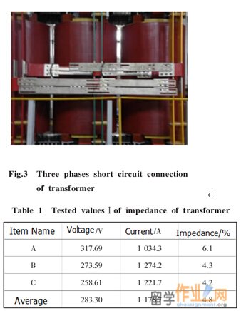
From table 1 the measured data, the measured impedance transformer value far exceeded the design value, up 4.8 percent, the average of the three-phase impedance serious imbalance, the maximum phase of 6.1%, 4.2% minimum phase. For this purpose, after preliminary analysis, that the main reason may be the following five aspects. The first is a three-phase transformer body impedance and impedance imbalance is too large. the second is a low voltage transformer winding two parts each implemented delta connection, and arranged in the upper and lower ends of the transformer leakage between nearby magnetic zone, copper windings and electromagnetic coupling, copper mutual inductance between the larger, increasing the fillet impedance copper itself. the third is a three-phase transformer copper fillet length and be relatively inconsistent ay short, while cx longer, resulting in a three-phase copper impedance imbalance. Fourth, low voltage transformer for each phase two vertical copper is actually the line current of each phase is divided into two branches, the two branch current of the same size, the same direction, alternating magnetic flux generated mutually reinforcing, while the two branches of the mutual inductance is large copper, increasing the vertical copper per phase impedance. Fifth is an impedance transformer short circuit test points Select the possible unreasonable.
The above analysis has decided to carry out targeted impedance test trials, in order to find the product of serious impedance measured value is too large and the three-phase impedance based on the real reason for the serious imbalance.
6 Field trials using the method of discovery, analyze problems场试验采用发现法,分析问题
6.1 Impedance test transformer body
Its purpose is the measured impedance transformer body is too large and the three-phase impedance is balanced! Specific operating angle $ remove two parts connected to the low voltage winding of copper and three-phase vertical copper, head directly to the upper and lower part of the low voltage transformer windings Department shorted, see figure 4, the measured impedance values transformer body see table 2.#p#分页标题#e#
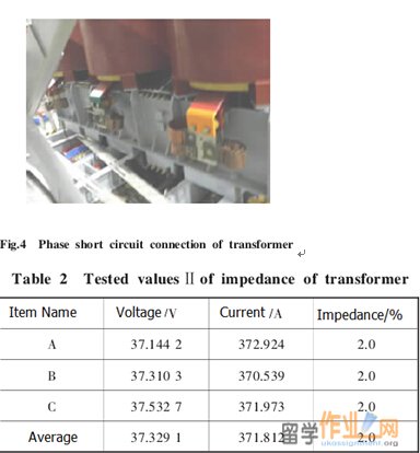
From table 2 shows the measured data, the impedance measured value is too large transformer body 5% than the design value of 1.9%, three-phase short-circuit impedance transformer body is balanced.
6.2 Low impedance test transformer body with vertical copper after
Its purpose is the measured voltage three-phase transformer impedance value copper vertical size and unbalance specific operations: installing low-pressure vertical copper, the upper and lower parts of the head and tail of the low voltage winding a1, a2, x1, x2, b1, b2, y1, y2, c1, c2, z1, z2 and vertical copper corresponding parallel, so that each of two vertical copper phase currents are equal in magnitude and opposite in direction. then shorting in the middle of each phase two vertical copper, see figure 5, the measured impedance values, see table 3.
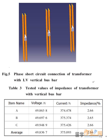
Measured data from table 3 shows that the three-phase transformer low impedance values vertical copper were 0.66%, 0.65% and 0.66%, three-phase balanced.
6.3 Transformer low impedance test leads were after delta
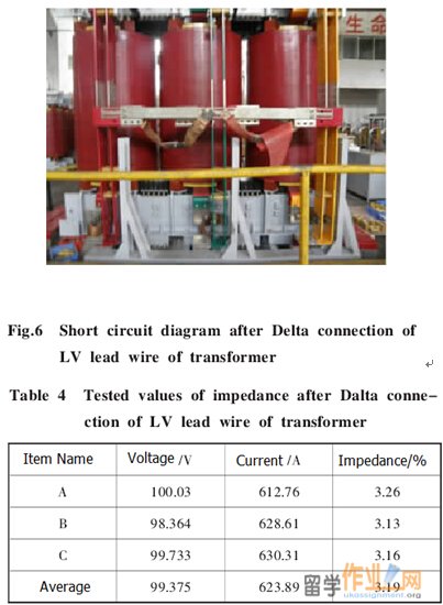
Its purpose is the measured voltage three-phase transformer impedance values of copper imbalance rate and transformer size and overall size of the impedance values and unbalance after row angular contact specific operation is in the middle of the outer row of vertical copper were triangular voltage three-phase connection, and then in fillet of central shorting copper, see figure 6. The measured impedance values see table 4.
Measured data from table 4 shows that the three-phase transformer low impedance values fillet after copper were 1.26% 1.13% and 1.16%, three-phase unbalance maximum rate of 6.5%. Transformer low copper wire impedance measured value of 1.19 %, close to the design value of 1.045% overall impedance measured value transformer larger than the design value of 6%, which is larger than the value of the project requirements 6%. Overall three-phase transformer impedance maximum unbalance rate was 2.2%, to meet project requirements.
At the same time, the test results also illustrate the following points. The first is an effective way to reduce the wiring impedance of the transformer, but also effectively eliminating the three-phase impedance imbalance. The second is that if the structure and the connection of figure 6 Low copper wire is shown in an ideal program.
7 Transformer impedance measured data structure improved变压器阻抗测量数据结构改进
According to figure 6 field test wiring, structural design transformer low copper wire were improved # cancel transformer low-voltage winding down the corner of two parts connected to copper, the upper and lower parts of the head and tail transformer low voltage windings a1, a2, x1, x2, b1, b2, y1, y2, c1, c2, z1, z2 corresponding parallel, then in the middle of the transformer to achieve vertical fillet copper and copper leads to a three-phase outlet in the middle position of the fillet.
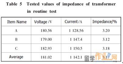
After the transformer low structural improvements lead copper production completion, the product of the impedance of the factory test, the three-phase short lead, the measured impedance values see table 5.
Measured data from table 5 shows the measured impedance value & transformer overall 5.7% larger than the value of the project requirements; a maximum of three-phase impedance unbalance rate was 1.6%, well positioned to meet the requirements of the project.
8 Conclusion总结 First, for low impedance transformer design calculations, to be based on the actual situation of using a variety of methods in order to achieve a comprehensive reduce the impedance of the purpose of controlling material costs.
Second, the low voltage for low voltage and high current, low impedance transformer, the transformer due to the impedance value is very small body; basically copper wire and low impedance copper qualifying structure and connections of the transformer in the same order of magnitude, low voltage transformer impedance prominent influence. the conventional impedance transformer impedance value due to the body, affecting the structure and connections of the low-pressure outlet copper transformer impedance is much smaller.
Third, for the low voltage and high current transformers, low voltage copper wire arrangement should be possible to phase current of each phase were divided into one or a few branches, so that the beginning and end of each branch currents are equal in magnitude and opposite in direction of copper staggered rows with each other, that is similar or identical to the same phase inverse parallel structure, to produce alternating magnetic flux cancel each other out, so that not only reduces the mutual inductance between the copper, but also greatly reduce the impedance of copper itself.
Fourth, low voltage and high current, and the user requirements for closed delta transformers, low voltage copper wire arrangement should be possible to make a three-phase copper bars are arranged outside of the fillet in the middle of a three-phase phase current copper, and in the fillet in the middle leads to a three-phase copper qualify, so the three-phase copper fillet alternating magnetic flux can cancel each other out a larger part, and in itself can reduce the mutual impedance between each fillet copper, but also can reduce impedance imbalance due to the length of the three-phase copper fillet inconsistencies caused.
The determination of the rated current for each load factors coated conductors is 70%. Although the non-uniform distribution Large current and ac losses of HTS wire in parallel Manufacturing transformer coil, the main problems in us assumptions and transposed conductor coating evenly distributed. The current, it can be through the wiring technology implementation Such as lobell bar when the increase of load in power network, lower voltage. Maintain network voltage at a constant level, the traditional power transformer are usually equipped with On-load tap-changer (OLTCs). On-load tap-changer power change Transformer turn ratio in a pre-defined steps and the secondary voltage change. Usually on behalf of each step changes in the low voltage side is 1.25%. Standard tap switch to provide 10% of the rated voltage of the change. Automatic adjustment of voltage, high temperature superconducting winding is designed the on-load voltage regulating transformer. A typical automatic voltage regulator (AVR) regulating voltage in the secondary side of power supply Transformer. Control method is based on the principle of a step by step. That is, a pulse control, at the same time, will be sent to the switch up or down load tap changing mechanism In the 65 K superconducting connected tap step position
The split winding can lead to thermal dissipation. So We design the on-load voltage regulating transformer tap choose to install the part of the equipment In liquid nitrogen and other parts of the installation at room temperature, in the traditional transformer. The installation
In the primary winding of the tapping point, it is divided into two cylindrical sections. High temperature superconducting transformer has four concentric Set the winding.
From inside to outside, there is a third winding, half of the primary. One, two, and the other half of the main is the Tapping point installed outside the primary winding and a half. In the half is by continuous winding and Combined with double flat winding and continuous Disc type winding. The outside of the semi continuouswinding there is no tapping point. Cooling of the transformer winding is by supercoiledliquid 65 K. But the temperature rise of winding Because ac losses in operation, so the operating temperature Been identified as 69 K of the vertical component of leakage In a high ac loss than parallel winding magnetic flux Points. AC should be restricted to a small loss Perhaps because of the cost of the cooling system is still too High. Therefore, winding structure optimization is Loss of communication. From this perspective, the double flat winding not considered useful. But bread double winding In a high pressure layer of advantage Power transformer insulation good and limitations, and so on Voltage stress. We put forward a new method of winding High pressure high temperature superconducting power transformer and is called continuous Disc type winding (CDW). It has the advantage of the two layers and Bread double winding. It can have multiple disks, as we want No joints between disc, not like double flat winding Primary, secondary and tertiary windingConcentric. The length of the radial clearance is according to the adjusted. Between the winding leakage impedance and voltage stress Transformer, high temperature superconducting transformer, until now have very low percentage Because ac losses of low impedance. But the field test
High temperature superconducting transformer, it should have internal impedance
This is from the requirement of power transmission system. In South Korea, Power companies need the percentage of 15% impedance 60 MVA transformers. Of 100 MVA superconducting#p#分页标题#e#
The impedance of the transformer, 12% is determined by previous studies the new high temperature superconducting power system, whendevice forhigh temperature super conducts transformer winding. The third winding is necessary Suppression of harmonic and compensates the third for secondary asymmetric load. For calculating
In coated conductor winding loss of communication, the same technologyBSCCO winding can be used. The parallel and vertical in the continuous winding magnetic field component are for the numerical calculation. From the vertical and exchange losses By the magnetic field, and parallel computing Plate model equation. The composition of the calculation of the AC loss is Magnetization losses and transport current losses. We calculated loss during winding, primary and secondary schools winding for rated current and the third winding arenot Behavior. When ac losses and the change of impedance percentage33 MVA super conducts transformer due to the change the gap between the winding.
AC loss, % 33 MVA HTS coil impedance High temperature superconducting transformer can from numerical analysis. Two dimensional numerical analysis is in an inter-bank High temperature superconducting wire assume more perfect transposition.
Reference文献
Abramovitz, A., & Smedley, K. M. (2012). Survey of solid-state fault current limiters. IEEE Transactions On Power Electronics, (5-6), 2770.
Borage, M. m., & Tiwari, S. (2013). A 25 kW, 25 kHz Induction Heating Power Supply for MOVPE System Using L-LC Resonant Inverter. Advances In Power Electronics, 1-10.
Du, W., Jiang, Q., Erickson, M. J., & Lasseter, R. H. (2014). Voltage-Source Control of PV Inverter in a CERTS Microgrid. IEEE Transactions On Power Delivery, 29(4), 1726-1734. doi:10.1109/TPWRD.2014.2302313
Duggan, P. (2006). Integration issues for fault current limiters and other new technologies- a utility perspective. 2006 IEEE Power Engineering Society General Meeting, 3. doi:10.1109/PES.2006.1709126
Dufournet, D., & Montillet, G. (2002). Transient recovery voltages requirements for system source fault interrupting by small generator circuit breakers. IEEE Transactions On Power Delivery, (2), 474.
Rifaat, R., Lally, T. S., & Hong, J. (2014). Circuit Breaker Transient Recovery Voltage Requirements for Medium-Voltage Systems With NRG. IEEE Transactions On Industry Applications, 50(5), 2989-2995. doi:10.1109/TIA.2014.2309175
Sauer, L. E. (1953). Duplex Current-Limiting Reactors: Their Application and Forces. Transactions Of The American Institute Of Electrical Engineers, Part III: Power Apparatus & Systems, 72(2), 1297. doi:10.1109/AIEEPAS.1953.4498768
Sen, P., & Sarunpong, P. (2001). Overloading and loss-of-life assessment guidelines of oil-cooled transformers. 2001 Rural Electric Power Conference. Papers Presented At The 45Th Annual Conference (Cat. No.01CH37214), B4/1-B4/8. doi:10.1109/REPCON.2001.949516
VASIREDDY ANVESH, D. R. (2013). Optimal Positioning of Superconducting Fault Current Limiters for the Smart Grid Application Using Simulink. International Journal Of Advanced Research In Electrical, Electronics And Instrumentation Engineering, (6), 2094.
Yunbing Wei1, e., & Dong Zhang1, z. (2014). Research on the On-line Measuring Method of Transformer Short-circuit Reactance. Advanced Materials Research, 981636-640.
|
| 网站地图 |