|
英国作业网专业指导英国assignment Contents 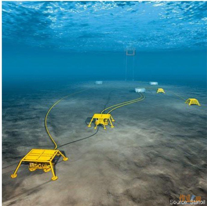 Subsea bulk water removal, with re-injection or disposal Subsea single-phase or multi-phase boosting of well fluids Subsea sand and solids separation and sand handling system Subsea gas/liquid separation and liquid boosting Subsea gas treatment Subsea gas compression Monitoring-, control- and instrumented safety systems. 7 The most important benefits of subsea processing are: Subsea separation with re-injection of produced water increases the oil production Subsea removal of water reduce or eliminate the need for water treatment equipment topside New marginal fields may be developed with a minimum of topside processing equipment Production from marginal fields or well testing can be performed using very simple FPSO’s. Injection of raw seawater eliminates the need for topside water injection pumps, a swivel path an FPSO and the water pipeline. Reduced risk of hydrate formation and less use of chemicals due to subsea water 6 removal Removing the water reduce the flow and the specific gravity of the fluid. The static head and the flow resistance decrease, allowing use of smaller pipelines and risers. Increased oil production potential Phased and cost effective development.52 1.3 Why use subsea processing? What is driving the interest in subsea processing? The macro factors including the following three factors: energy demand, oil prices and the growth of offshore production. The large energy demand worldwide and especially by developing countries driving the world oil demand growth, which will cause a tightening oil supply and subsequently lead the price to increase. Driven by the high profits, companies around the world are turning to deepwater prospects to replace their fields on continental shelf. And there is a trend to rely on the high-technology and cost-effective subsea approaches to accelerate production and boost reserves8 At the same time, while it is possible to find more oil resources in marginal fields, deep water and even arctic areas where 25% of the world's undiscovered oil and gas reserves are reserved9, the conventional Oil & Gas exploitation and processing method reveal its limitation in exploring these new fields. As subsea processing is insensitive to deepwater fields and reserves in remote or harsh environments, it will be the final solution to explore those new areas. Besides, with a decrease in production in shallow waters, more and more companies are trying to find new oil and gas fields in deeper water, where the cost of conventional fixed or floating facilities can be very expensive, thus providing an incentive to develop subsea processing systems.#p#分页标题#e# 7 The decrease of production in shallow-water drives people to explore areas in deep water 9 Energy demand The increase of demand for oil, especially for developing countries like China. The growing supply of gas, which reflects the growing importance of gas9 8 Oil prices The price of oil increases rapidly in recent years9 2003 oil companies global spend $148 billion; 2004 forecast spend grows to $159 billion (+7.5%); 2005 initial indications of 8% to 10% growth.) 9 9 Growth of offshore production. The growing demanding of oil drives the overall amount of production to increase 9 1.4 Where can Subsea Processing being used? As we are clear with the advantage of Subsea Processing now, the question comes to where we can use these technologies. And with the advantages we have mentioned above about Subsea processing, these technologies are usually applicable to the following three situations: Marginal fields: Marginal fields are typically small reservoirs with complex geology and limited production potential, which makes conventional platforms economic unfeasible. Tie-ins to existing infrastructure: The geometry and depth of a reservoir may be such that some parts cannot be reached from a platform using conventional drilling techniques or horizontal wells. Deep water and arctic developments: Subsea production units offer the advantage of being less sensitive to the water depths and harsh surface conditions. 10 10 2. Technologies involved in the subsea process 2.1 Subsea Production Systems. 2.1.1 An Overview of Subsea Production Processing. A subsea oil and gas production system (SPS) includes most of the main elements found in a conventional platform production system, but is unique when it comes to remoteness in installation, service and operation. 11 Subsea development from pore to process:12 11 Here as an illustration, we may show the basic procedure of subsea processing to tie a marginal field to an existing infrastructure. Because most of the marginal reservoirs are not large enough to justify the expense of a dedicated processing facility, operators would like to take advantage of existing infrastructure by tying marginal-field production back to platforms that serve other field. Due to high pressure and low temperature at seabed, sometimes artificial lift may be required to raise the produced fluid to subsea wellhead or tree. To accommodate with the temperature of subsea tree, produced fluid need to electrically heating up or being transported by foam-insulated pipe. Then fluid enters a flowline jumper that connects to a production manifold. Before reaching the subsea manifold, the produced fluid may pass through a multiphase flowmeter used to measure production form each well, then Fluid from all production wells mixed together before entering the manifold. Then the produced fluid will pass through a subsea booster pump before being sent through a flowline and up a production riser.#p#分页标题#e# 2.1.2 Subsea Manifold Manifold is a unit which purpose is to interconnect all modules by means of piping and electrical cables. The manifold may contain pumps, multiphase meters and de-sander typically. As for all modules, the manifold is retrievable for maintenance and/or repair.13 Manifold 14 12 Numerous Manifolds and Foundation Structures based on standard building blocks, but at the same time customized to meet the various field and customer requirements.15 2.1.3 Connection systems: The range of Subsea Connection System features diversely connectors and tooling system to meet various application requirements to connect flowlines and umbilicals to equipment like Christmas-tree or subsea manifold. The core of every connection system is the connector itself, along with its sealing system. The three main types of connectors are: • Clamp connectors • Collet connectors • Mandrel connectors16 2.1.4 Subsea Tree Systems Subsea trees & control 13 The subsea tree is the primary well control module providing a mechanism for flow control and well entry. Typically, the subsea tree is controlled through a multi-plexed electro-hydraulic control system. The functions of a tree are activated and monitored through a SCM (Subsea Control Module). Typically this module is interfaced to the control system via Tronic pod base connectors. It is vital for effective reservoir and production management that information on the tree status and operating conditions are fed back to the master control station. Typically, measured variables are pressure, temperature, flowrate, valve position, choke position and sand production rates. 17 Tree systems are designed from standard “building block” components to meet exacting standards and requirements ranging from less than 100 ft up to 10,000 ft water depths. Tree configurations include simple diver assist shallow water mudline trees (TOM) up to drill through and deepwater guideline less horizontal trees (HT) and vertical or conventional trees. Tree system designs can accommodate reservoir shut in conditions of 350ºF and 15,000psi and in the other extreme provide facilities for electrical or hydraulic submersible pumping systems (ESP / HSP), or artificial lift by gas or water.18 2.1.5 Flow Assurance To reach a processing facility, produced water need to be transported under high deep-ocean pressures and cold temperatures. As deep ocean wells are often of depths 305 m to 3048 m or greater, produced fluid experiences significant changes in pressure and temperature when it moves form pore space to production riser. Moving produced high viscosity produced fluid dominated by heavy fraction of hydrocarbons is difficult. Any number of factors, acting singly or in concert, can lead to scale, hydrate, asphaltene or wax deposition in subsea flowlines. These deposits can be severe enough to impede flow to surface processing facilities.#p#分页标题#e# 14 The onset and magnitude of flow-assurance problems are largely influenced by the chemical compositions of produced fluids and by their temperatures and pressures as they travel from one end of a production system to the other. These problems can be mitigated by taking flow assurance measures to anticipate and manage conditions that affect hydraulic performance of production systems. Production assurance can be divided into three interrelated functions: flow assurance, flow assurance and flow surveillance. The assurance needs measurement of pressure, temperature, flow rate and other variables, and the feedback will be analyzed to give control to the operation of pumps, chemical injectors and other components to optimize performance of the production system. 19 2.2 Control and Monitoring Control system is a system for operating and monitoring the subsea processing system. A subsea control system usually consists of two main components and connections between them. The two main components are Subsea Power and Communication Unit and the Subsea Control Unit. 15 Subsea power and communication unit is a unit positioned on a platform or onshore to transfer electrical power communication between onshore and subsea system, and Subsea Control Unit is a control module that is used for controlling the subsea processing system. The subsea control unit communicates directly with the topside control system. The control system is connected to other equipment through umbilicals in order to receive signal from measurement equipment like multiphase flowmeter and to control equipment like the pump systems to give action. 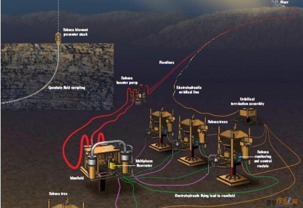 In deepwater subsea developments, surveillance data provide the information needed to make the decisions that enhance efficiency, increase productivity, and reduce risk. The surveillance including the monitoring of temperature, pressure, strain, vibration, shape, flow, and fluid properties, etc. 20 2.2.1 Umbilicals Umbilical Cores Umbilicals are used strictly to provide services from surface to subsea: electrical power signals hydraulic pressure 16 In the sixties, the umbilicals supporting these early wells were direct-hydraulic, with a large number of hydraulic cores (one for each tree valve). In the Seventies multiplexed electro hydraulic control systems were introduced, permitting much smaller umbilicals. Up to the eighties, umbilicals still see many problems exist: Leaks from connections and hydraulic fittings; Permeation from methanol hoses into other hydraulic cores and cables; Hose collapse; and water ingress into electrical cables and connectors. In the Nineties: This decade saw the introduction of steel tubes and fibre optics. The steel tubes eliminated the failure modes of thermoplastic hoses at a stroke (leaks, permeation, and hose collapse). Fibre optics gave umbilicals the potential for greatly increased distances for signal transmission.21#p#分页标题#e# Umbilical termination assembly A multi-plexed electro-hydraulic system allows many subsea 17 control modules to be connected to the same communications, electrical and hydraulic supply lines. The result is that many wells can be controlled via one umbilical, which is terminated at an Umbilical Termination Assembly (UTA) stabplate. From the UTA, the connections to the individual wells and SCMs are made with jumper assemblies. For long stepout distances it is recommended that cable assemblies are utilised. 22 Pressure intensifiers Pressure intensifiers can reduce the number of hydraulic lines nee in an umbilical. these devices have been successfully used on a number of subsea developments.23 2.2.2 Signal Transmission Signal Transmission is one of the most arcane areas of umbilical and control systems. The range achievable with signals multiplexed onto the power line is limited, and the number of wells that can be interfaced to such a system is also limited. But this type of system has the benefit of minimizing the number of copper cables needed in the umbilical. Splitting signals and power onto two separate cables can achieve greater distances, as 18 crosstalk (noise) getting onto the signal lines is substantially reduced. but this technology will probably never be further developed due to advances in other areas. Fiber optics gives a quantum leap in bandwidth, greatly increased range, and immunity to electrical interference. Fabre optics is a revolution to the subsea umbilical systems.24 2.2.3 Multiphase Flow Meter Multiphase flow meter is a device that can register individual fluid flow rates of oil and gas when more than one fluid is flowing through a pipeline. A multiphase meter provides accurate readings even when different flow regimes are present in the multiphase flow. 25 Multiphase Meter 26 Subsea multiphase flow meter provides data on the well performance and eliminates the need for a separate test line and topside test separator. The unit measures and provides on-line information on the fraction of oil, water and gas. The meter can be electrically interfaced to a subsea production control system or in a separate, dedicated control umbilical. 2.3 Subsea Flow Boosting A Subsea boosting system is a system used to increase pressure in flow pipes in order to enhance the flow-capacity. Basic components of a boosting system are the interconnected pumping system and re-injection system. 27 19 2.3.1 Why do we need subsea boosting? For Oil: Subsea oil pressure boosting can provide the following benefits: Enables ultradeep light oil production; Enables deep heavy oil production; Increases ultimate recovery for deep light oil and may be used reduce flow assurance costs . 28 Increase of Production due to Boosting 29 In all cases, subsea boosting reduces or eliminates the backpressure on the wells from the riser hydrostatic head and riser and flowline viscous pressure drop.#p#分页标题#e# Although most reservoirs have sufficient pressure to produce to the seafloor without the use of downhole artificial lift, many ultradeep light oil and deep heavy oil reservoirs are near hydrostatic pressure and cannot produce to the sea surface under their own pressure for more than a short period of time. Subsea oil pressure boosting is broadly applicable to deepwater subsea oil projects. And it is proven in moderate water depths to roughly 3000 feet, depending on desired boost pressure, gas content and viscosity. 28 For Gas: Gas compressor is used to lower the volume and increase the pressure of export gas in subsea applications. The pressure increase can be used to pump the gas to remote production facility and the reduction in gas volume can enable use of the pipeline with 20 smaller inner diameter. For gas fields, the reservoir pressure drops over time eventually necessitating gas boosting to recover the remaining reserves. The industry is increasing its focus and efforts on subsea gas compression technology. This represents potential cost savings compared to building an offshore platform to host the compressor. Subsea gas dewpointing and dehydration can be used as follows. Reduce flow-assurance costs by eliminating or minimizing the need for continuous hydrate inhibition. Reduce pipeline costs by removing water to allow use of carbon steel rather than a corrosion-resistant alloy. Process gas to sales quality, which also addresses flow-assurance needs. 30 2.3.2 Types of boosting systems in use Electrical-Submersible-Pump (ESP)/Caisson System: In this system, an ESP is installed in a dummy well or caisson on the seafloor. The caisson may be used as a gas/liquid separator to accommodate high-gas/oil-ratio (GOR) oils, or without separation for lower-GOR oils. The key limitations are limited pump power available for ESPs and relatively high intervention cost and time compared with seafloor modular pumping systems. In addition, ESPs are inefficient for heavier oils. Helicoaxial Multiphase Pump. The helicoaxial multiphase pump is a roto-dynamic pump capable of boosting lighter oils that have relatively high gas-volume fractions, with boosting capability up to approximately 1,000 psi. As suction pressure drops, the gas-volume fraction increases and liquid-volumetric efficiency declines accordingly, limiting the practical achievable suction pressure and, therefore, ultimate recovery. Because this system is on the seafloor, larger motors are practical, intervention is simpler, and costs are lower compared to an ESP/caisson. 21 Twin-Screw Pump. This positive-displacement pump is capable of boosting heavy oils efficiently but is inefficient for light oils. Boosting capability is limited to approximately 1,000 psi. Although the pump can operate with very high gas-volume fraction, as suction pressure drops, gas-volume fraction increases and volumetric efficiency declines. This trait limits the practical achievable suction pressure and, therefore, ultimate recovery.#p#分页标题#e# Riser Gas Lift. Riser gas lift is a relatively low-cost method of providing lifting capability. Generally, it can achieve less lift and, therefore, less ultimate recovery than a pumping system. Cooling effects from gas expansion in the riser may limit applicability at greater water depths, especially for low-temperature reservoirs. 31 2.3.3 Subsea injection systems Injection system refer to the re-injection of water, gas or/and sand back to a injected well. raw seawater injection system The system consists of a single retrievable liquid pump module with a filtration module that is separately retrievable from the pump module. The liquid pump is a centrifugal multistage type and is driven by a water-filled motor. The filter unit is self-cleaning with hydraulic actuator and a water purging system. The pump can be delivered horizontally for lower fishing friendly structures or vertically for reduced footprint. 22 Gas and liquid separation with liquid boosting system The system is a subsea processing system for separating the gas and liquid phases of well fluid, followed by pressure boosting of the liquid phase. Each of the phases is transported to the host facility topside through separate risers. 32 Sand Injection In case of sand production, it is not preferable to bring it through the pipeline all the way to the offshore or onshore receiver due to risk of erosion damages to pipeline, valves, etc. A method of sand disposal is to re-inject the sand together with the produced water. This method will also provide an environmental benefit.33 2.4 Subsea separation Separation system is a system designed for separating fluids and gas from a multiphase fluid. There are two major types of separation: two phase separation to split gas and liquid, and three phase separation splitting oil gas and water. 34 2.4.1 Why use subsea separation Subsea Separation - value drivers: For maturing fields, an investment in a subsea processing station can contribute to 23 increased earnings, production and recovery, improving and prolonging the use of existing infrastructure. For new field developments, subsea processing can provide cost-efficient and environmentally friendly platform-free solutions, where the field is tied in to an existing offshore facility or directly to shore. The CDS compact subsea separator facilitates cost-efficient design by using a patented gas bypass and state-of-the-art topside proven internals.35 The Gravity Separation Module with CDS Separation Technology36 2.4.2 Common separators Subsea gravity separator: A subsea separator using gravity segregation to separate the different phase which means the heaviest fluid settles to the bottom and the lightest fluid rises to the top. Subsea centrifugal separator: A subsea separator which separates the different phases by rotating the multiphase fluid. The different phase will then be distributed along the rotation radium as a function of the phase's self-weight. 36#p#分页标题#e# Centrifugal Separator 37 24 2.4.3 Downhole oil/water separation and reinjection system This system is a separation and re-injection system which is integrated on the production well. 38 A subsea separation plant is based on a standard template structure with a modularized design for the separator, pump and power distribution. A subsea separator is installed downstream the wellheads to separate the water which is then re-injected in a separate well. Removing the water from the oil reduces the process flow; thereby reduce the dynamic pressure drop. As the specific gravity of fluid is reduced, the static backpressure in the riser is reduced as well. The water taken re-injected to the well can be used as pressure support in the reservoir, eliminating or reducing the need for topside water injection systems.39 Water re-injection system40 2.5 Power transmission and distribution Subsea electric power distribution system usually includes the topside equipment, the power transmission system and the subsea power distribution. Electric power is suited for both short and long distance applications. In case of short distance, direct supply is normally used. In long distance applications, electric power is taken in a single high voltage umbilical to a step-down transformer located at the 25 subsea structure. The low voltage power is then distributed locally to each consumer via subsea frequency converters. 41 2.5.1 overview of subsea power systems GE Oil & Gas The increasing requirement for subsea processing and boosting in relation to efficient field development has generated the need for highly reliable subsea power and distribution systems. The growing power requirements to enable efficient and economic boosting of hydrocarbons have demanded significant development in power systems. 42 Dry mate connections: The subsea dry mate connection is a vital part of the high voltage termination system and can be used in pressure compensated systems or as a high pressure barrier to penetrate a pressure vessel. The subsea wet-mateable connector is a highly reliable connector for hign voltage power cable for subsea applicatons. This connector uses the Dry Mate cable termination technology and has a unique in-situ dielectric conditioning system for 26 the connector internals. This ensures a reliable make-up subsea.43 2.5.2 Subsea power supply systems The subsea electrical equipment seen so far is mainly control systems, but some pumps with voltages up to 6.6 kV are in operation. Upcoming field developments will demand steadily higher power at longer distance from existing infrastructure or shore. This will lead to a demand for reliable subsea high voltage equipment and frequency converters. Major and fundamental challenges in the power supply area are related to pressurized frequency converters, the influence of humidity, temperature and pressure on insulation material lifetime, high voltage design for components, test/qualification methods for electrical equipment to be used subsea, methods for extended range AC transmission and systems for DC transmission.#p#分页标题#e# Local power generation is not considered realistic at the moment, but may be an option in the future.44 2.5.3 Power transmission Electrical Power Transmission Trend to 3 phase power and DC. Today’s technology can supply (at 36kV AC) 30 MVA up to 50 km 20 MVA up to 250 km Future requirements can be met by increasing AC voltages and by DC transmission 27 Electrical power transmission presents no difficulties for umbilical systems. Virtually any necessary step out or power demand can be met with present equipment. There is a trend towards DC transmission of electrical power. This is more efficient as AC dielectric losses in the cables are avoided. The equipment vendors are starting to manufacture and promote DC control systems. Electronics and solid state power circuits have greatly facilitated the application of DC power distribution.45 2.5.4 subsea power distribution Electrical Power Distribution: A unit used for distributing electrical power to the various consumers such as pumps, separator motors, compressors, etc. 46 Subsea Power Distribution 47 3 Case Study of StatoilHydro Tordis Subsea Processing system 3.1 General Facts about Tordis: This oil field lies in block 34/7 in the Tampen area of the Norwegian North Sea, and came on stream in 1994. In addition to the main Tordis structure, the development embraces the Tordis East (1998), Borg (1999) and Tordis South East (2001) fields. These discoveries have all been developed with subsea installations. Water depth is roughly 200 metres. 28 Water injection is used to maintain pressure in the reservoirs. Oil from Tordis is piped to the Gullfaks C platform 10 kilometres away for processing, storage and export. The former Saga Petroleum company became operator for licence PL 089 when the licence was awarded in 1984. Norsk Hydro took over operatorship after acquiring Saga in 1999. Statoil took over operatorship on 1 January 2003, and from 1 October 2007 the operatorship has been assumed by StatoilHydro.48 3.2 Project Overview: Project Characteristics No. Trees: 1 Water Depth: 200 m (656 ft) Tree Type: Water Injection XT Separator Design Pressure 200 bar (2900 psi) 29 Tree Pressure: 5,000 psi Hydrocarbon: Water Disposal Scope of Work •One (1) pipeline inline manifold (PLIM) interconnecting the existing flowlines from the Tordis field to Gullfaks C platform •One (1) new design large capacity water injection subsea tree •One (1) Subsea separation, de-sanding and wear resistant •Subsea boosting system for multi-phase flow and water injection, including instrumentation for performance •Monitoring and process control •Approximately 12 km (7 miles) control umbilical •Approximately 12 km (7 miles) power umbilical •Topside HPU’s for pumps and control system •Topside VSD’s for power to pumps subsea •Topside process control system •System integration, testing, installation assistance, service and maintenance#p#分页标题#e# 3.3 Detailed system description 30 System Description: Pipeline Inline Manifold (PLIM) The PLIM will be installed summer 2006 to interconnect the flowlines from the Tordis Subsea Manifold to the Gullfaks C platform allowing re-routing of the Tordis Well Stream to Gullfaks C via the Subsea Separation Station. The PLIM allows full bypass of the Tordis Subsea Separation, and will be installed during a planned maintenance shut-down of the Gullfaks C Platform Water Injection Tree The Water Injection Tree is a simple Xmas Tree consisting of a 12” ball valve. A conventional internal tree cap is installed in the vertical entry section of the tree allowing for workover of the well. The reinjected water is pumped through this Xmas Tree through a 13 5/8 casing direct into the Utsira water reservoir. This is a non hydrocarbon reservoir with ambient pressure. Subsea Separation Boosting and Injection (SSBI) Station The Subsea Separation Station separates the water from the well stream which is reinjected through the large bore Water Injection Tree. After separation, gas and oil is mixed and pumped via a multiphase pump back to the Gullfaks C platform. The SSBI Station is installed in October 2007. The Separation Station contains the following main elements: Foundation Structure and Manifold The Tordis SSBI Station has an independent conventional, overtrawlable foundation structure supporting the manifold, the separation module and all other components. The structure has four suction anchors, one in each corner for foundation and leveling. The manifold module provides connection to the flowlines via Rovcon connection system and interconnects the various modules. The estimated installed weight of the Subsea Separation Station with manifolds and separation modules is approx. 900 tons. Separation Module The well fluid from the Tordis field is first routed into the separation tank. The inlet cyclone separator in the tank does a first separation where the majority of the gas is 31 separated out and routed through a separate pipe outside of the tank, thereby minimizing the size of the separation tank. The remaining water, oil and gas are separated through the gravity principle inside the tank. The water is the heaviest part which is pumped via a water injection pump directly back into the Utsira reservoir through the Xmas Tree. Oil and gas are remixed and pumped through a multiphase pump back to the Gullfaks C platform. Any deposit of sand inside the separation tank is handled by the sand removal system. The Separation Module is retrievable as a separate unit. Sand Removal System Any sand from the well stream will deposit at the bottom of the separation tank. A flushing system with specially designed nozzles has been developed to flush out the sand at certain intervals. The sand is transported into the Desander Module where it can be remixed with the injection water and reinjected into the reservoir downstream of the water injection pump. Alternatively the sand can be remixed with the oil and gas flow and pumped back to the Gullfaks C platform.#p#分页标题#e# Water Injection Pump The Water Injection Pump is a standard Framo pump system which is driven by an electrical motor powered through an electrical power cable from the Gullfaks C platform. The pump can be retrieved for maintenance by a separate pump running tool. Multiphase Pump The Multiphase Pump is a standard Framo pump, similar to the Water Injection Pump, and is powered through an electrical power cable from the Gullfaks C platform. It can also be retrieved by a separate pump running tool. Other The Subsea Separation Station is equipped with two multiphase flow meters (Roxar) which will measure the composition of the well flow to prepare the separation system settings. A level monitoring system is installed in the separation tank to monitor water, oil and gas interfaces which again provide input to the water pump speed and the multiphase pump speed. The Subsea Separation Station 英国作业网专业指导英国assignment includes one subsea control32 module with 51 functions to control the various functions of the station and communicate back to the Gullfaks C platform. 3.4 Comment: FMC has delivered a full scale separation facility to enable re-injection of bulk water into a non-hydrocarbon reservoir and send hydrocarbons through a multi-phase pump back to Gullfaks C. The system including boosting pumps has been designed to handle high amounts of sand (50 - 500 kg per day) with its sand management system. Along with other upgrades to the field infrastructure, the recovery factor for the Tordis field is expected to increase from 49% to 55% (approximately 35 million barrels). The PLIM was installed during the field shutdown summer 2006. The water injection tree was installed early 2007 and the subsea separation, boosting and injection system summer 2007. Tordis Subsea separation Boosting and injection station is now on stream.49 4 Conclusion: 4.1 From the Technological Aspect. Although for over 20 years subsea processing has been poised as one of the most potentially promising technology developments in the offshore industry50, this is still an initiatory technology and most of the subsea processing implementation is still limited to multiphase pumping and bulk water separation. Many technical problems like long-distance transmission of power and signal is still unreliable.51 Also challenges rise up on the high cost of construction of new system. The reduced production level of current mature field will also challenge people to extend the field to marginal areas to make full use of the existing infrastructures. So we can see there is still a big space of R & D on Offshore Oil & Gas Technology. 33 4.2 From the Oil & Gas demanding Aspect As we have mentioned above, the future demanding for resource especially on Oil and Gas will increase very rapidly, which will stimulative the price to rise up. The high profit will eventually drive the oil traders to find out ways to increase the production. The exploitation to oil and gas resource in area with harsh environment will also accelerate the advance of Offshore Oil & Gas Technology.#p#分页标题#e# 4.3 Comments. Both from the aspect of current technology level and the aspect of future resource demanding, we can forecast Offshore Oil & Gas Technology to be a very promising technology and will be developed rapidly. 5 References 1. GE Oil & GAS. Subsea Field Development. Retrieved Sep 26, from: http://www.geoilandgas.com/businesses/ge_oilandgas/en/prod_serv/systems/subsea_production/subsea_field.htm 2. FMC. Subsea processing. Retrieved Sep 26, from: http://www.fmctechnologies.com/Subsea/Products/IOR/SubseaProcessing.asp 3. Jan Olav Hallset. Poseidon. Subsea Processing Terminology. Retrieved Sep 28, from: http://posccaesar.vestforsk.no/intra/Portals/0/reports/processing.pdf 4. Gene Kliewer. (2007). Offshore. Tordis becomes world’s first subsea processing installation. Retrieved Sep 28, from: http://www.offshore-mag.com/index/article-display/315249/s-articles/s-offshore/s-volume-67/s-issue-12/s-top-five-projects/s-tordis-becomes-worldrsquos-first-subsea-processing-installation.html 5. Lead Party Statoil.( 2006).Technology strategy for Subsea Processing and Transport . Retrieved Sep 28, from: http://www.forskningsradet.no/servlet/Satellite?blobcol=urldata&blobheader=application%2Fpdf&blobheadername1=Content-Disposition%3A&blobheadervalue1=+attach 34 ment%3B+filename%3D537558TTA6.pdf&blobkey=id&blobtable=MungoBlobs&blobwhere=1229378544960&cachecontrol=5%3A0%3A0+*%2F*%2F*&ssbinary=true 6. Gene Kliewer. (2007). Offshore. Tordis becomes world’s first subsea processing installation. Retrieved Sep 28, from: http://www.offshore-mag.com/index/article-display/315249/s-articles/s-offshore/s-volume-67/s-issue-12/s-top-five-projects/s-tordis-becomes-worldrsquos-first-subsea-processing-installation.html 7. FMC TECHNOLOGIES. Subsea Processing. Retrieved Sep 28, from: http://www.fmctechnologies.com/Subsea/Products/IOR/SubseaProcessing.aspx 8. Ian Gallett.(2005). Society for Underwater Technology. Global Offshore Prospects#p#分页标题#e# Retrieved Sep28, from: http://events.sut.org.uk/past_events/2005/0504201/programme.htm 9. Offshore Technology. The Subsea Processing Promise. Retrieved Sep 29, from: http://www.offshore-technology.com/features/feature1412/ 10.POSEIDON. Subsea Processing Terminology. Retrieved Sep 29, from http://posccaesar.vestforsk.no/intra/Portals/0/reports/processing.pdf 11. POSEIDON. Subsea Processing Terminology. Retrieved Sep 29, from http://posccaesar.vestforsk.no/intra/Portals/0/reports/processing.pdf 12.http://www.slb.com/media/services/resources/oilfieldreview/ors05/spr05/01subsedevelopment.pdf 13. POSEIDON. Subsea Processing Terminology. Retrieved Sep 29, from http://posccaesar.vestforsk.no/intra/Portals/0/reports/processing.pdf 14.http://www.offshore-engineer.com/fileadmin/images/article_content/OE_Issues/current_cover/May_2009/July_2009/gll_2000_3h.jpg) 15.GE Oil & GAS. Subsea tree systems. Retrieved Sep 26, from: http://www.geoilandgas.com/businesses/ge_oilandgas/en/prod_serv/systems/subsea_production/subsea_field.htm 16.GE Oil & GAS. Subsea tree systems. Retrieved Sep 26, from: http://www.geoilandgas.com/businesses/ge_oilandgas/en/prod_serv/systems/subse 35 a_production/subsea_field.htm 17. Expro. Electrical submersible pumps. Retrieved Sep 29, from: http://www.exprogroup.com/index.php?option=com_content&task=view&id=59&Itemid=78 18. GE Oil & GAS. Subsea tree systems. Retrieved Sep 26, from: http://www.geoilandgas.com/businesses/ge_oilandgas/en/prod_serv/systems/subsea_production/subsea_field.htm 19.http://www.slb.com/media/services/resources/oilfieldreview/ors05/spr05/01_subsea_development.pdf 20. POSEIDON. Subsea Processing Terminology. Retrieved Sep 29, from http://posccaesar.vestforsk.no/intra/Portals/0/reports/processing.pdf 21. Paul Smy.(2005). Society for Underwater Technology. Cost Effective Manifolds Retrieved Sep28, from: http://events.sut.org.uk/past_events/2005/0504201/programme.htm#p#分页标题#e# 22. Expro. Electrical Submersible Pump. Retrieved Sep 28, from: http://www.exprogroup.com/index.php?option=com_content&task=view&id=59&Itemid=78) 23 Paul Smy.(2005). Society for Underwater Technology. Cost Effective Manifolds Retrieved Sep28, from: http://events.sut.org.uk/past_events/2005/0504201/programme.htm 24. Paul Smy.(2005). Society for Underwater Technology. Cost Effective Manifolds Retrieved Sep28, from: http://events.sut.org.uk/past_events/2005/0504201/programme.htm 25. POSEIDON. Subsea Processing Terminology. Retrieved Sep 29, from http://posccaesar.vestforsk.no/intra/Portals/0/reports/processing.pdf 26. POSEIDON. Subsea Processing Terminology. Retrieved Sep 29, from http://posccaesar.vestforsk.no/intra/Portals/0/reports/processing.pdf 27. POSEIDON. Subsea Processing Terminology. Retrieved Sep 29, from http://posccaesar.vestforsk.no/intra/Portals/0/reports/processing.pdf 28. Dennis Denny. (2006). JPT ONLINE. Subsea Processing and Boosting - Technical 36 Challenges and Opportunities. Retrieved Sep 29, from: http://www.spe.org/spe-app/spe/jpt/2006/08/subsea_tech3_18261.htm 29. FMC TECHONOLOGY. Subsea Processing. Retrieved Sep 28, from: www.fmctechnologies.com/upload/subsea_processing4.pdf 30. FMC TECHONOLOGY. Subsea Processing. Retrieved Sep 28, from: www.fmctechnologies.com/upload/subsea_processing4.pdf 31. Dennis Denny. (2006). JPT ONLINE. Subsea Processing and Boosting - Technical Challenges and Opportunities. Retrieved Sep 29, from: http://www.spe.org/spe-app/spe/jpt/2006/08/subsea_tech3_18261.htm 32. AKER SOLUTIONS. Subsea processing and boosting. Retrieved Sep 30, from: http://www.akersolutions.com/NR/rdonlyres/03A80E3F-0BAE-41AB-AC12-ABC9C09C645C/16190/Subseaprocessingandboosting.pdf 33. POSEIDON. Subsea Processing Terminology. Retrieved Sep 29, from http://posccaesar.vestforsk.no/intra/Portals/0/reports/processing.pdf#p#分页标题#e# 34. POSEIDON. Subsea Processing Terminology. Retrieved Sep 29, from http://posccaesar.vestforsk.no/intra/Portals/0/reports/processing.pdf 35. FMC TECHONOLOGY. Subsea Processing. Retrieved Sep 28, from: www.fmctechnologies.com/upload/subsea_processing4.pdf 36. FMC TECHONOLOGY. Subsea Processing. Retrieved Sep 28, from: www.fmctechnologies.com/upload/subsea_processing4.pdf 37. Offshore Technology. Processing, Separation, Filtration and Water Treatment. Retrieved Sep 30, from: http://www.offshore-technology.com/contractors/separation/gallery.html 38. POSEIDON. Subsea Processing Terminology. Retrieved Sep 29, from http://posccaesar.vestforsk.no/intra/Portals/0/reports/processing.pdf 39. POSEIDON. Subsea Processing Terminology. Retrieved Sep 29, from http://posccaesar.vestforsk.no/intra/Portals/0/reports/processing.pdf 40. POSEIDON. Subsea Processing Terminology. Retrieved Sep 29, from http://posccaesar.vestforsk.no/intra/Portals/0/reports/processing.pdf 41. Technical Bulletin. Increased oil production in means of Subsea Processing. 37 Retrieved Sep 27, from: http://www.ukassignment.org/daixieAssignment/daixieyingguoassignment/42. GE Oil & GAS. Subsea tree systems. Retrieved Sep 26, from: http://www.geoilandgas.com/businesses/ge_oilandgas/en/prod_serv/systems/subsea_production/subsea_field.htm 43. GE Oil & Gas Business.Subsea processing and power system. Retrieved Sep 26, from: http://www.gepower.com/businesses/ge_oilandgas/en/prod_serv/systems/downloads/sspps.pdf) 44. TTA. (2006). Technology strategy for subsea processing and transport. Retrieved Sep 27, from: http://www.forskningsradet.no/servlet/Satellite?blobcol=urldata&blobheader=application%2Fpdf&blobheadername1=Content-Disposition%3A&blobheadervalue1=+attachment%3B+filename%3D537558TTA6.pdf&blobkey=id&blobtable=MungoBlobs&blobwhere=1229378544960&cachecontrol=5%3A0%3A0+*%2F*%2F*&ssbinary=true#p#分页标题#e#) 45. Paul Smy. (2005). Society for Underwater Technology. Cost Effective Manifolds Retrieved Sep28, from: http://events.sut.org.uk/past_events/2005/0504201/programme.htm 46. Jan Olav Hallset. POSEIDON. Subsea processing terminologies. Retrieved Sep 29, from: (http://posccaesar.vestforsk.no/intra/Portals/0/reports/processing.pdf) 47. Schneider. subsea power distribution module. Retrieved Sep 30, from: http://www.schneider-electric.com/sites/corporate/en/solutions/business_segments/oil-and-gas/oil-and-gas-upstream-extraction/subsea-power-distribution-module.page) 48. StatoilHydro. Facts about Tordis. Retrieved Oct 2, from: http://www.statoilhydro.com/en/ouroperations/explorationprod/ncs/tordis/pages/default.aspx) 49. FMC TECHNOLOGIES. StatoilHydroTordis. Retrieved Oct 2, from: http://www.fmctechnologies.com/Subsea/Projects/Norway/StatoilTordis.aspx 38 50. Offshore Technology. The Subsea Processing Promise. Retrieved Sep 26, from: http://www.offshore-technology.com/features/feature1412/ 51. TTA. (2006). Technology strategy for subsea processing and transport. Retrieved Sep 27, from: http://www.forskningsradet.no/servlet/Satellite?blobcol=urldata&blobheader=application%2Fpdf&blobheadername1=Content-Disposition%3A&blobheadervalue1=+attachment%3B+filename%3D537558TTA6.pdf&blobkey=id&blobtable=MungoBlobs&blobwhere=1229378544960&cachecontrol=5%3A0%3A0+*%2F*%2F*&ssbinary=true) 52 Technical Bulletin. Increased oil production in means of Subsea Processing. Retrieved Sep 27, from: http://www.framoeng.no/Files/Bulletins/SubseaProcessing.pdf 6. Appendix Subsea Processing Terminologies: Boosting system definitions: Boosting system: A system used to increase pressure in flow pipes in order to enhance the flow-capacity. Electrical Submersible pump: An artificial-lift system that utilizes a downhole pumping system that is electrically driven. The pump typically comprises several staged centrifugal pump sections that can be specifically configured to suit the production and wellbore characteristics of a given application.#p#分页标题#e# Multiphase pump: A pump which is capable of pumping fluid consisting of several phases. e.g. oil, gas, water and sand. The pump can be of screw-type or piston-type. Helico-axial pump: A pump with several pump stages, each consisting of a rotating 39 helical shaped impeller and a stationary diffuser. The helico-axial pump can be regarded as a hybrid between a centrifugal pump and an axial compressor. Twin-Screw pump: A pump which creates a volume chamber by the intermeshing of two rotating screws. Mixer: A device that mixes the multiphase flow to a homogeneous fluid. The mixer will be positioned upstream of the multiphase pump and usually integrated in the multiphase pump itself. Multiphase flow meter: A device that can register individual fluid flow rates of oil and gas when more than one fluid is flowing through a pipeline. A multiphase meter provides accurate readings even when different flow regimes are present in the multiphase flow. Subsea gas compression: A system that increases the pressure of the produced gas for pressure boosting or reinjection in the reservoir. The main purpose of the gas compression is to increase total gas production. Gas cooler: a unit which is used for cooling the produced gas prior to compression in order to increase compression efficiency and also reduces gas temperature after compression. Scrubber: A device to remove dirt, water, foreign matter, or undesired liquids that are part of the gas. The scrubber is used to protect downstream rotating equipment or to recover valuable liquids from gas. Gas compressor: A device that raises the pressure of air or natural gas. A compressor normally uses positive displacement to compress the gas to higher pressures so that the gas can flow into pipelines and other facilities. 40 Anti Surge Valve: a valve which purpose is to regulate the compressor's inlet pressure to avoid large and sudden pressure changes. Injection system definitions: Injection system: An arrangement of injecting fluid or gas into a well. Injection well: A well in which fluid are injected rather than produced, the primary objective typically being to maintain reservoir pressure. Two main type of injection are common: gas and water. Separated gas from production wells or possibly imported gas may be re-injected into the upper gas section of the reservoir. Injection of produced water: After separation of water from the well stream, the produced water can be injected to maintain reservoir pressure. Major benefits gained from re-injecting the produced water is less total flow from seabed to installation and no environmental impact. Injection of seawater: A seawater pump is connected to an injection well n order to pump seawater into the reservoir to maintain sufficient pressure. Seawater treatment including electro-chlorination, desecration and particle filtration is required prior to injection. Gas Injection: Produced or imported gas is injected into the upper section of the reservoir in order to maintain sufficient pressure.#p#分页标题#e# Sand Injection: In case of sand production, it is not preferable to bring it through the pipeline all the way to the offshore or onshore receiver due to risk of erosion damages to pipeline, valves, etc. A method of sand disposal is to re-inject the sand together with the produced water. This method will also provide an environmental benefit. 41 Separation system definitions: Separation system: A system designed for separating fluids and gas from a multiphase fluid. There are two major types of separation: two phase separation to split gas and liquid, and three phase separation splitting oil gas and water. Subsea Separator: A cylindrical or spherical vessel located at seabed in order to separate oil, gas and water from the total fluid stream produced by a well. Subsea gravity separator: A subsea separator using gravity segregation to separate the different phase which means the heaviest fluid settles to the bottom and the lightest fluid rises to the top. Subsea centrifugal separator: A subsea separator which separates the different phases by rotating the multiphase fluid. The different phase will then be distributed along the rotation radium as a function of the phase's self-weight. Subsea cyclone separator: A subsea separator used for separating gas from oil/water using supersonic flow. A swirl created in the supersonic flow regime centrifuges the fluid to the wall and hence separates the gas form the oil/water. A gravity separator can be positioned downstream of the cyclone to split oil and water. Downhole oil/water separation and reinjection system: A separation and re-injection system which is integrated on the production well. Electrical system definitions: Transformer Unit: A unit to transform high voltage power supply to low voltage for local distribution. Due to distant positioned subsea processing system, high voltage electrical supply is used to minimize power loss. Electrical Power Distribution: A unit used for distributing electrical power to the 42 various consumers such as pumps, separator motors, compressors, etc. High Voltage connector: A connector which represents the interface between power-umbilical and process system. Special designed to handle high voltage supply required by the processing system. Hybrid Connector: A connector which is able to connect both electrical, optical and hydraulic lines. Control system definitions: Control system: A system for operating and monitoring the subsea processing system. Subsea power and communication unit: A unit positioned on a platform or onshore to transfer electrical power communication between onshore and subsea system. Subsea Control Unit: A control module that is used for controlling the subsea processing system. The subsea control unit communicates directly with the topside control system. Well System definitions: Well system: a drilled bore to be used for production or injection of fluids, gas or material.#p#分页标题#e# Production Well: A well which oil and/or gas are produced from. Injection well: A well in which fluid are injected rather than produced, the primary objective typically being to maintain reservoir pressure. Two main type of injection are common: gas and water. Separated gas from production wells or possibly imported gas may be re-injected into the upper gas section of the reservoir. 43 Template definitions: http://www.ukassignment.org/daixieAssignment/daixieyingguoassignment/Template System: A steel Structure designed for installation of subsea modules. The subsea template is designed for installation by use of mud-skirt, suction anchors or piling. The design of the template allows easy installation and retrieval of the modules for maintenance or repair purpose. Manifold module: A unit which purpose is to interconnect all modules by means of piping and electrical cables. The manifold may contain pumps, multiphase meters and de-sander typically. As for all 英国作业网专业指导英国assignmentmodules, the manifold is retrievable for maintenance and/or repair. |
| 网站地图 |